Wednesday, May 30, 2018

USB keyboard (Backlit) LED light- Method 2

"USB keyboard (Backlit) LED light-Method 2"


Hey guy's today I will show hoe to make an USB keyboard Backlit LED light by another method.
Now let's make it.

Requirements :-
Following are the things you required to do this project.
1. LED's
2. Old USB cable
3. Switch
4. 4K7 ohm resistors
5. Wires
6. soldering gun and cutter

How to make it :-

1. First we need to take out the power supply wires of the USB cable.Follow the steps of the method 1 from my previous post to do this.


2. Measure the length of the laptop's keyboard and connect two LED's on both end of the laptop in parallel connection.
The circuit diagram is as shown below.


3. Connect two more LED's on the other side also. This will looks like below.


4. You can use thin laminated wires to to the connection also. So that wires will not be visible.

5. When you done with this, take the switch and connect wires to it. Connect negative terminal of  USB to the negative terminal of LED's which is common.

6. Connect the 1K resistor to the common  positive terminal of the LED's. Also add the switch next to it. Finally connect other terminal of the switch to the positive terminal of USB.


7. Now you are ready with your keyboard backlit.

8. Connect the USB slot and turn ON the switch. And you can see all key's of the keyboard in dark also.


Hope you will enjoy this project.

Thank you for reading...

Monday, May 28, 2018

USB keyboard (Backlit) LED light- Method 1

"USB keyboard (Backlit) LED light- Method1"


Hello guy's. Today I am going to show you how you can make keyboard backlit by using LED's. This is a very simple and interesting project to do.

Introduction :-
 Many laptops or computers don't have keyboard backlit. Some times we have to work on laptops during nights. But typing in dark is a very difficult task. You can't see which key you are pressing.


The picture is showing the condition in the dark. You can't see anything here on your keyboard.
But don't worry, here is one of the solution to make your keyboard illuminate in dark so you can enjoy typing during dark also without bothering others.


Requirements :-
Following are the things you required to do this project.
1. 2 to 3 LED's
2. Old USB cable
3. Switch
4. 4K7 ohm resistors
5. Wires
6. soldering gun and cutter
7. Old ballpen refill


How to make it :-
Follow the steps given below.

1. Take the old USB cable. Open the upper casing of USB.


2. Use cutter or the screw driver to open cover from USB.


3. As you can see there are total four wires are present, Red, White, Green and Black. Here the Red wire is positive supply voltage and Black is the ground wire. Both the wires conducts 5 volt from charger to the phone.
The remaining two wires are the data carrying wires when you connect your laptop to the charger for data exchange.

4. Sometimes the upper casing of the USB is not removable. So cut the wire and open the four wires out.


5. Now cut the data wires. Hence when we connect the USB into the laptop USB slot, it will generate 5 volt across the red and black wires.

6. Now take two LED's and connect then into parallel combination. Connect the resistor to the positive lead of the LED's.


7. Now connect the wires to the LED's negative terminal and the resistors remaining terminal.
The wires I have used are thin laminated wires. You can get it from old transformer's winding.


8. Solder the wires. Now take the refill and remove the tip of refill.


9. Drop the wires through the refill. Connect black tape to the top remaining part of the LED side.


10. Now connect the two wires to the USB cables. Take care of the polarity. Glue the refill on the USB so that it will stood straight on the USB. Tape the open wires after soldering.


11. The circuit diagram will looks like this.


12. Now you are ready with your own keyboard backlit.

13. Connect the USB into laptop. And you can see that LED's glows. Adjust the LED's so that they are directed towards keyboard.


14. Here you can see that anyone can easily see the key's on the keyboard. Also you can change the angles of the LED's for a particular region.

15. Further you can add more LED's for more brightness. Also you can add a switch to turn ON and OFF LED's when you need.
Hope you enjoy this project.

Thanks for reading...

Tuesday, May 22, 2018

About Me


Hello guy's, myself  "Nikhil Narayan Asogekar".
I have completed my Electronic Engineering degree from KIT's College of Engineering.
I have designed this page primarily for students and also for people who enjoy making different projects. So I keep sharing various interesting projects, this will also develop our knowledge.

mail-id:- tech3nik@gmail.com

Hope you guys enjoy my page. Keep commenting, keep sharing, keep learning.

Let's make it...
Thank you...   

Monday, May 21, 2018

Arduino 3x3x3 LED cube

               "ARDUINO 3x3x3 LED CUBE"


Hello friends. Today we are going to make a 3x3x3 LED cube project. This project is based on the arduino. Now let's do it.

Requirements :-

27 LED's
9 resistors - 1K ohm each
A general purpose PCB board
Arduino uno board
Soldering gun
Wire cutter
Connecting Wires


Now let's start making.

Follow the steps given below:-

1. First we have to connect LED's in a proper format.
2. Take a thick cardshit paper. Draw a 3x3 square pattern on it. As shown below.


3. This will acts as a base for your LED model.

4. Now place all 9 LED's in each slot.


5. Then connect the negative (i.e. shorter) terminal of each LED to the next LED as shown. And keep the positive terminal as it is.


6. Here we are connecting negative terminals of all LED's together. After soldering, take out the first layer which will looks like as shown.


7. Form such three layers. Now place one layer on the top of other such that all 9 positive terminals of upper layer will just touch the 9 positive terminals of the layer below. And solder them.


8. Now you will see that there are total 9 columns and 3 rows.

9. Connect the cube on PCB.

10. Give numbering as shown.


11. Now connect wires to each columns and rows. So there will be total 9+3=12 wires.

12. Connect 1K resistor to each column wire. This will form our setup.


13. Now let's focus on the coding.

The code is given as below.


14. Now connect the columns 1 to 9 to the pins of arduino from  1 to 9.

15. Connect three rows to pins 13,12 and 11 respectively.

16. Carefully do the connections. Avoid any mismatch.

17. Now burn the code into the arduino. And you can see different patterns are generating on the LED cube.


Hope you like the project.

Thank you for reading...


(Some images are taken from other sources for better understanding. )

Sunday, May 20, 2018

Homemade Power Bank

           "HOME MADE POWER BANK"


Hey guys, today I am going to show you how you can build a very low budget homemade power bank. Lets see how it's made.

Requirements :-


1. USB connector (From old charger or you can buy it).
2. 9 volt battery
3. IC 7805
4. Switch
5. 4k7 ohm resistor
6. LED
7. Wires

Now let's do it :-
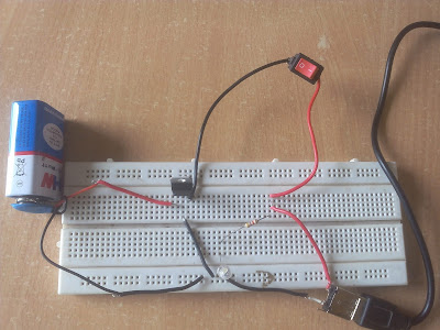
For clear idea the circuit is connected on a bread board.

1. The USB connector has four connections as shown below. The last two connections are the power supply connections in which we are interested in. The middle two are used for data transfer.


2. Connect the red and the black wires to the positive and negative terminal of the USB connector.


3. Now the IC 7805 is an DC voltage regulating IC, which takes upto 30v DC input and will supply 5v DC output. It has three pins i.e. input, ground and output respectively.

4. Build the circuit as shown in the diagram below.


5. It will be looks like as below.


6. Now connect the mobile and turn ON the switch. The mobile will start charging.


7. Further you can add filtering capacitors across the IC 7805.

Connect the whole circuit into compact form and you can easily carry your own power bank.
Enjoy making...


Thank you for reading...


Saturday, May 19, 2018

Selecting Arduino board

                "SELECTING ARDUINO"

Going to buy an arduino board...
There are lots of duplicate clones also presents. Now you might be in trouble to select the correct one. No worry here is the basic way to find the right one...
The actual arduino uno ATmega328P board looks just like this


Now look closely. You will find a golden fuse just below the USB power jack(as circled).
In case of cloned copies, this fuse is of green color.


So now there will not be any problem in selecting the appropriate board one.


Thank you for reading...


Soldering gun using pencil

      "SOLDERING GUN USING PENCIL"


Hi guy's, today we are going to do a very interesting project that is soldering gun out of a pencil. Sometimes our soldering gun stops working but don't worry here is the instant solution.
Now lets do it.

Requirements:- 

1. Pencil or graphite rod(From old battery cell)
2. wires
3. Battery(9v) or old phone charger(5v)
4. Cutter or blade


Steps to do :-
1. Now take the pencil and using blade cut the upper wooden part from one side of the pencil as shown in picture.


Or the best way you can take out the graphite rod present inside the battery cells.


2. Now connect two wires to the rod as shown.


3. Add some tape on the pencil so that it will be easy to hold it and it also provide safety for us.

4. Connect the battery to the wires. Or we can use the old phone charger as a power supply.

5.  Let the rod heat for some time.

6. Now try the gun on soldering wire. Yeah it melts...


Hope you enjoy doing this project.
Thanks for reading...

(Some images taken from internet)

Mini Tesla Coil

                       "Mini Tesla Coil" Hello friends, today we are going to make an mini version of the Tesla coil....